
|
Search | FAQ | US Titles | UK Titles | Memories | VaporWare | Digest | |||||||
| GuestBook | Classified | Chat | Products | Featured | Technical | Museum | ||||||||
| Downloads | Production | Fanfares | Music | Misc | Related | Contact | ||||||||
| Cooling Fan Installation for RCA 400 Series Interactive Players | ||||||||||||||
This page provides instructions for installing a cooling fan in RCA's SJT400 and SKT400 players. In contrast to other J/K players, these models have an extra circuit board in the form of a sandwich, that provides the additional circuitry needed for the interactive remote functions. The On Screen Display (OSD) integrated circuit on this board is subject to overheating, which usually results in a washed out appearance to the video image after the player has been on for a few minutes to an hour. There are several reasons why this OSD chip has a tendency to overheat.
This heat-related failure seems to be on the rise with 400 series players, so I've been investigating ways to overcome it. There are several methods to dissipate heat from the OSD chip, but the installation of a small fan inside the sandwich directly between the U6103 and U6101 chips seems to be the best approach in terms of simplicity and effectiveness. But all the various approaches to fixing this heat failure problem are discussed below.
Replace the OSD integrated circuit
The main problem with this approach is finding a replacement chip. Check for availability on the CED Parts page. If unavailable, it will have to be scavenged from an SJT400 or SKT400 parts machine. And simply replacing the chip doesn't address the overheating problem that is continuing to decrease the number of OSD chips that still work.
Operate the player in the service position
This allows the separated halves of the PW6100 board to freely dissipate heat, and an OSD chip that exhibits heat failure after a length of time with the player closed may not fail in the service position. But the player cannot be operated in this position on a continuous basis because of the risk of the exposed electronics.
Install a heat sink on the OSD chip
A heat sink will provide some heat dissipation, but I found it only gave an extra few minutes before the heat failure occurs. Heat sinks aren't as effective on plastic package IC's as they are on ceramic, and the upside down orientation of the OSD chip and the tight spacing also limit the effectiveness of a heat sink.
Operate the player inside a refrigerator
I mention this because someone sent me email stating their player, that exhibited heat failure of the OSD chip the instant it was turned on, would work normally when operated inside the kitchen refrigerator. This works because the OSD chip is cooled down to about 40 degrees F and is kept pretty cool by the refrigerated environment. But operating the player inside a refrigerator cannot be recommended due to the condensation likely to occur as the player interior cools down after use. And unless some system employing IR-RF-IR conversion is pieced together, the interactive remote features of the player will be unavailable.
The one use for this technique is to test whether installing a Peltier junction is feasible on players that exhibit immediate heat failure at room temperature. If the failure goes away when the player is turned on after sitting in the refrigerator for a few hours, then installation of a peltier junction may be feasible.
Install a peltier junction on the OSD chip
A peltier junction is a semiconductor the size of a postage stamp that when energized gets cold on one side and hot on the other side. This is the same type of cooling element found in the compact refrigerators intended for automotive and boat use. If the heat failure occurs within seconds after the player is turned on at room temperature, a peltier junction may be the only practical means to cool the OSD chip. The difficulties with the peltier junction are its power dissipation and the robust air circulation required to keep the side against the OSD chip cool. A peltier junction requires as much current as the entire CED player which must be supplied by a separate external power supply. And two cooling fans need to be installed, one adjacent to the heat sink on the hot side of the peltier junction, and another to suck the additional heat out of the player chassis.
Install a small cooling fan inside the PW6100 sandwich
This approach is much simpler than using a peltier junction, and it completely eliminated the heat failure on a test player the consistently failed about 20 minutes after being turned on. The reminder of this page describes the installation of such a fan in detail.
CAUTION: This procedure requires working on the exposed electronics of a CED player. Be familiar with, and adhere to these guidelines before proceeding:
The first step in installing a cooling fan is to place the player in the service position, a procedure that is basically the same for all J/K players. These instructions and Black & White photographs come from the RCA service literature.
(1) If cabinet top has been removed, remove receiver spindle assembly. Also remove stylus cartridge and store in safe place. Place instrument, bottom up, on workbench with soft surface.
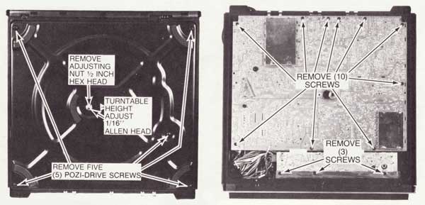
(2) Remove adjusting nut (1/2" hex head) and reinforcing plate (1-1/4" washer) from center of bottom cover (see upper left photo).
(3) Remove five (5) pozi-drive screws (see upper left photo).
(4) Lift off bottom plate and set aside.
(5) Remove thirteen (13) pozi-drive screws (see upper right photo).
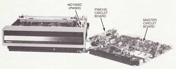
(6) Remove main circuit board and PW6100 by lifting front edge up to approximately a 10 to 15 degree angle, so as to clear all obstacles, then move board forward towards front of instrument until antenna connectors clear rear edge of base plate.
(7) After circuit boards are clear of base plate, rotate boards horizontally 90 degrees and lay beside instrument.
(8) Turn bottom plate over and fasten in position on base plate with adjusting nut and reinforcing plate removed in step (2) above.
NOTE: Bottom plate must be installed in prescribed manner to operate instrument in service position.
(9) Place instrument and circuit board in upright position, reinstall receiver spindle assembly and if front panel was removed reconnect front panel flex cable to flex cable connector. Instrument is now in operational service position (see photo below).
(10) To reassemble - reverse procedure.
CAUTION: Replace circuit board mounting screws only in holes from which they were removed (see upper right photo).
|
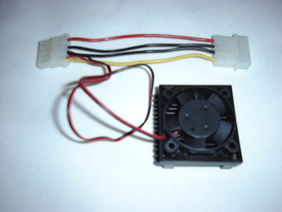
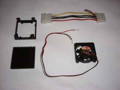
Assembled CPU Cooling Fan I obtained the required fan at a local computer store in the form of a CPU cooling fan intended for installation on the microprocessor in a desktop computer. This was actually cheaper than buying the fan alone from a mail order supplier like Jameco. If you buy the fan locally, take a ruler along to make sure the fan measures 1.6 x 1.6 x 0.4 inches. |
|
Disassembled CPU Cooling Fan Here is the fan separated from the heat sink and fastener on the left and the power supply tap above, none of which are required for the CED player installation. Note that the fan is a 12 Volt unit if the red lead from the fan goes to the yellow lead on the computer power supply tap. If it goes to the red lead on the computer power supply tap, the fan is a 5 Volt unit. The voltage will usually be printed on the fan as well. |
|
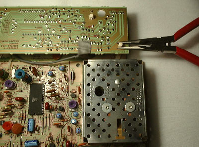
Separating the PW6100 Sandwich RCA's service position instructions don't mention how to separate the two halves of the PW6100, so this photo shows the start of the procedure. There are four locking spacers holding the two halves of the board together. Grasp the right most spacer with a small pliers and squeeze the jaws shut. At the same time lift the board up to just clear the jaws. Proceed to the next spacer until all four have been loosened and the boards are separated. |
|
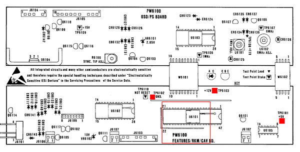
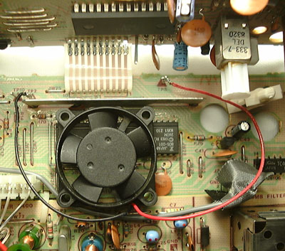
Fan In Place on PW6100 Board In this picture the fan has been installed on the lower portion of the circuit board. It rests on top of the U6101 Features Microcomputer IC and against the bus bar immediately above the fan. When the boards are closed, the U6103 OSD IC (visible at the very top of the picture) is positioned just over the top of the fan. Note that the fan is installed with the exposed center hub facing up. The exposed hub must be facing up to prevent it from rubbing against the board as the fan spins. In this position the fan sucks air around U6103 and blows it down around U6101. The fan leads can be seen soldered to GND (TP2) and +12V (TP3) as this is a 12 Volt fan. Be careful not to solder the black ground lead to TP10 which is just to the left of the TP2 ground test point. Note the routing of the thick gray cable going just under the lower left corner of the fan. When the two board halves are brought together this cable is used to loosely secure the fan against the metal bus bar above the fan. |
|
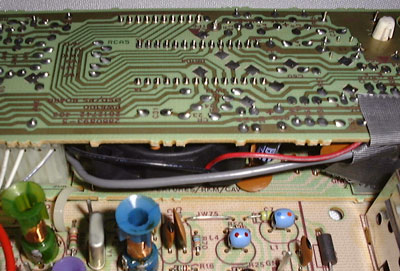
Fan Installed Inside the PW6100 This final photo shows the fan inside the closed halves of the PW6100 board. Note that the gray cable has been moved to the middle of the fan's side to hold the fan in place. Observe the group of three ribs on the edge of circuit board just above the fan which are an artifact left over from the manufacturing process. A small brown capacitor can be seen just below the left most of the three ribs. This is C6131 (labeled C31 on the board) and it should be bent flat against the board to prevent interference with the fan. Power the player up while in the service position to verify proper operation of the fan prior to reassembling the player. |