
|
Search | FAQ | US Titles | UK Titles | Memories | VaporWare | Digest | |||||||
| GuestBook | Classified | Chat | Products | Featured | Technical | Museum | ||||||||
| Downloads | Production | Fanfares | Music | Misc | Related | Contact | ||||||||
| Toshiba Turntable Motor Pulley Replacement | ||||||||||||||
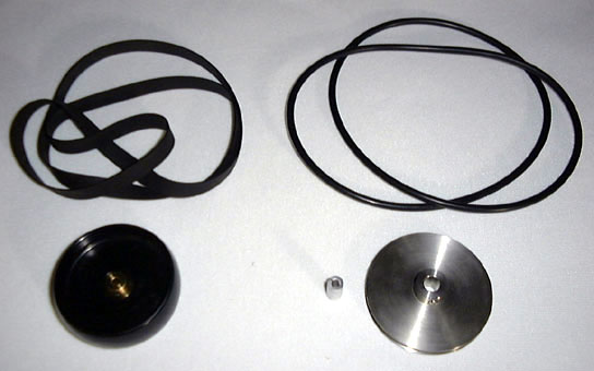
These instructions are for replacing the flat belt and pulley driving the turntable in Toshiba-manufactured CED players with a more reliable round belt and grooved pulley. The flat OEM Toshiba parts are shown above on the left, while the round replacement items are shown on the right (the small cylindrical item is a bore reducer). Although the unflanged pulley on the left is indeed designed to drive a flat belt, its intended use is in situations where both pulleys are in fixed positions, so the up-down motion of the turntable in Toshiba players increases the likelihood the belt will fall off. Toshiba overcame this problem by using a special wide belt with a slight curl on the inside (the outside is marked with a white stripe), but these belts have been unavailable for years, and the only option has been to use a narrower belt.
I've had the narrower belt available for some time on the CED Player Belt Ordering Form, but users of this replacement have found that it falls off every few hours, usually at a disc load or unload. It may seem a simple matter to just put the belt back on again, but the tight clearance in the Toshiba VP100 and its clones makes this a difficult task. RCA F/G players also employ a turntable design the exhibits up-down motion, but RCA used a flanged pulley to drive a rather narrow flat belt. This design does require one adjustment not necessary in the Toshiba players, as the turntable motor mounts have to be set so the belt rides in the center of the pulley.
These instructions replace the flat belt and pulley with a round belt and grooved pulley that eliminates the belt fall off problem. The procedure is applicable to all Toshiba manufactured players including the VP100, VP500, and VP550, as well as the Elmo VEC-200 and Wards GEN10301. The instructions are written for the VP100 player and its Elmo and Wards clones, but can be easily adopted to the Toshiba VP500 and VP550. These last two players came late in the player production cycle and represent only about 1% of the Toshiba players in existence. Their design is greatly simplified in comparison to the earlier models as there is no system control board above the turntable. Each installation step in the instructions notes the differences that apply to the VP500/550. The parts required for this installation are available in the online store at Stock Drive Products/Sterling Instrument (SDP/SI) and are as follows:
| Catalog No. | Description |
| S1086Y-PC-05 | Precision Grooved Pulley, 2.0" Outer Diameter w/ 0.25" Bore |
| A 7A30-250312 | Inch to Metric Bore Reducer, 0.25" Outer Diameter w/3mm Bore |
| A 6R11-04084 | Round 1/8" Endless Belt, 8.5" Inside Diameter |
Note that the bore reducer is used to achieve a 2" pulley with a 3mm bore that exactly matches the diameter of the turntable motor shaft in the Toshiba players. SDP/SI can custom bore a 2" pulley to 3mm, but this costs much more than buying the stock parts. If you look through the SDP/SI catalogs you may see 2" pulleys with a 0.125" bore. This is larger than 3mm and will function in the Toshiba players, but avoid using this imprecise match. The loose bore means the pulley on the fast spinning turntable motor will be wobbling slightly, and this wobble will shorten the life of this difficult to find motor. Also avoid using plastic pulleys, as these have a large hub that interferes with proper positioning on the motor shaft. If you obtain the round endless belt from another source, check the Durometer rating. The SDP/SI belt has a hardness of 70 Durometer and this indicates an optimal 15% stretch for the belt in the 30.75" drive path of the Toshiba players. The calculation 30.75 / 3.14 x 0.85 = 8.3 reveals the nearest inside diameter of 8.5" is the proper choice. Some round belts are 90 Durometer with a 7% optimal stretch. The calculation for 90 Durometer is 30.75 / 3.14 x 0.93 = 9.1 which indicates the nearest 9.0" inside diameter is optimal.
You might wonder what will happen if these large diameter round belts become unavailable at some time in the future. I don't see that happening anytime soon because round belts have a wide range of industrial applications and are available in these sizes from many other suppliers besides SDP/SI. Even if the stock belts become unavailable, a belt of any desired size can immediately be made from 1/8" round fusible Polycord, where the desired length is cut and the two ends are heated up and pressed together forming a permanent bond.
This procedure also requires a few tools. A 1.5mm hex key is required to loosen the socket head screws on the flat belt turntable pulley, and a 1/16" hex key is needed to tighten the single screw on the precision grooved pulley. All other screws require a medium Phillips driver. Before proceeding, be sure to unplug the player, and keep it unplugged until step (16). Touch the metal chassis of the player periodically to discharge any static electricity building up on your body, and while working around the system control board minimize contact with the electrical components. A lot of different size screws are removed in the steps that follow. Organize them by grouping them in a line as they are removed. When you're ready to reassemble the player the screws can be easily identified by their order in the line.
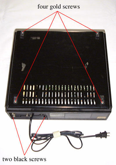 (1) Position the player up-side-down and remove the four gold-colored screws from the bottom of the player. Then remove the two screws above the connections panel on the back of the player. Lift the bottom cover off the player.
VP500/550: Remove the two screws to either size of the connections panel on the back of the player. The bottom cover does not have to be removed.
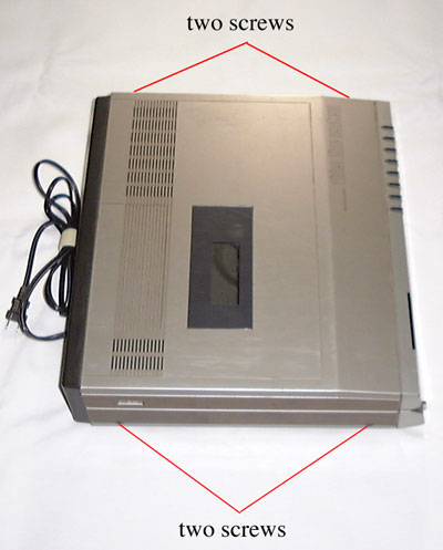 (2) Position the player right-side-up and remove the two screws on the left side of the player and the corresponding two screws on the right side of the player. Lift the top cover off the player and work the power cord through the opening in the cover.
VP500/550: Perform this same step, but the power cord doesn't need to be worked through an opening.
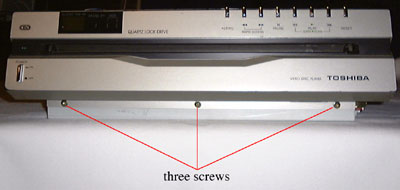 (3) Remove the three screws from the lower portion of the front panel.
VP500/550: Ignore this step.
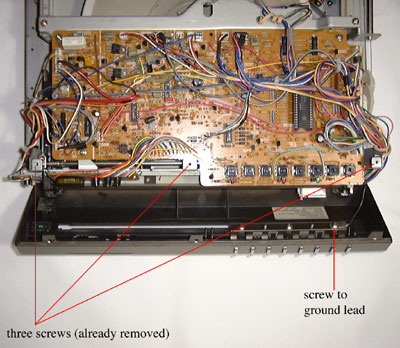 (4) Remove the three screws from the top of the front panel and slip the panel forward. Remove the single screw securing the ground lead and set the panel aside.
VP500/550: Ignore this step.
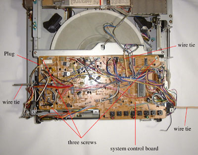 (5) Unfurl the three wire ties, then remove the three screws securing the system control board to the player chassis. Disconnect the first electrical plug (P515) at the upper left corner of the circuit board. Most players have a fixed nylon cable tie on the left side of the circuit board in addition to the wire tie. If this nylon tie is absent it won't be necessary to unplug P515. The wire ties and plug are removed to give the circuit board some wiggle room for the next step.
VP500/550: Ignore this step.
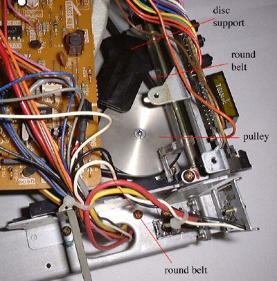
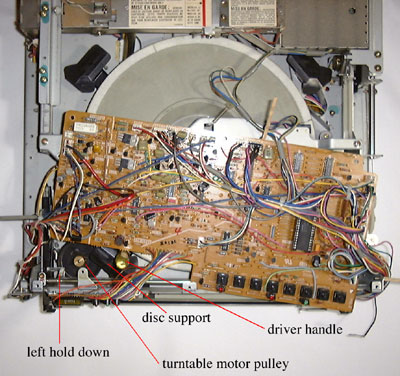 (6) Rotate the system control board so the screw holding the disc support can be reached, then remove the screw and work out the disc support, which is keyed opposite the screw. This picture shows the handle of a yellow driver in position on the screw. It may be necessary to carefully lift up on the wires on the left hand side of the system control board to clear the electrical components.
CAUTION: Never plug the player into an AC outlet with the system control board rotated. This position shorts some leads to the chassis ground, and the components could immediately fail if power were applied.
VP500/550: With no system control board in the way, the disc support screw can be directly accessed as soon as the player cover is removed.
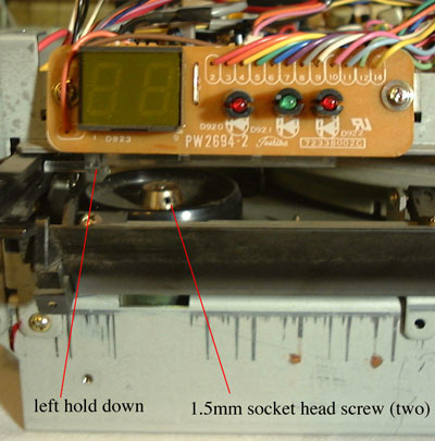 (7) Hold the caddy insertion door open and reach through the door opening with a 1.5mm hex key to loosen the two socket head screws on the top of the turntable motor pulley. Rotate upward the clear plastic hold down immediately above the motor pulley, then remove the turntable motor pulley from the motor drive shaft.
VP500/550: The motor pulley socket head screws can be directly accessed from above.
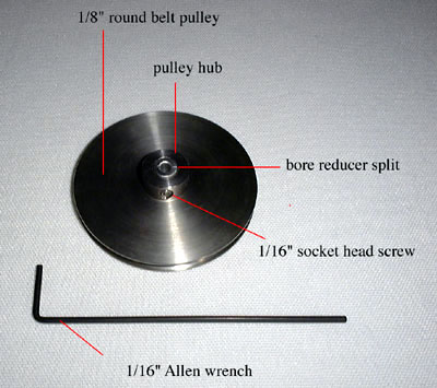 (8) Use a 1/16" hex key to loosen the socket head screw on the new motor pulley, and insert the bore reducer evenly between the top and bottom, tightening the screw just enough to keep the bore reducer from slipping. The split in the bore reducer should be at a 90 degree angle to the tightening screw as shown in the illustration.
VP500/550: Perform this same exact step.
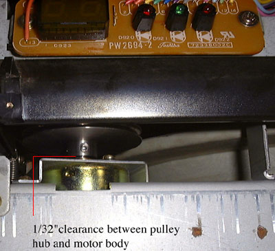 (9) Install the new motor pulley on the drive shaft with the hub facing down, and tighten the screw from underneath the caddy door opening. The top of bore reducer should be about 1/32" below the top of the motor drive shaft and there should be about 1/32" of clearance between the pulley hub and the drive motor body.
VP500/550: Tighten the socket head screw from inside the player.
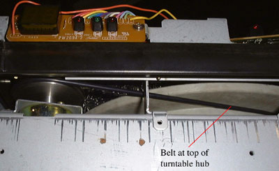 (10) Install the round drive belt by first placing it around the turntable hub and then around the turntable motor pulley. The drive belt should be resting at the very top of the turntable hub, as the turntable will rise to move the disc into the play position.
VP500/550: Perform this same exact step.
 (11) Reinstall the disc support, then spin the turntable around a few times to confirm that it rotates freely and the belt rides at the top of the turntable hub.
VP500/550: Perform this same exact step.
(12) Put the system control board in the proper position and reinstall the three screws illustrated in step (5). Wrap the three wire ties back into place and reconnect electrical plug P515.
(13) Position the front panel near the front right corner of the player and reconnect the ground lead. Slide the front panel into place and reinstall the three screws illustrated in step (4).
(14) Reinstall the three screws at the lower portion of the front panel illustrated in step (3).
(15) Stand the player on its right side and place the bottom cover back in position (with the ventilation grill to the rear of the player). Tilt the player slightly and reinstall the four gold-colored screws illustrated in step (1), starting with the two at the top.
(16) Lay the player down in an upright position, and plug it into an AC outlet. Load a disc and verify proper turntable operation.
(17) Unplug the power cord and work it through the opening on the back of the player cover. Lower the cover into place and reinstall the four screws on the sides of the player and the two screws above the connector panel on the rear of the player. You're done!